Slug tuned inductors

This side presents some facts about slug tuned inductors I have been measure the inductance for different winding turns.

All contribution to this page are most welcome Fabr Neosid typ 7x1S The 7V1S type which I have been testing has a frequency range from 50-200MHz. The AL value for this coil is 4,5 nH/n2 The color of the slug is Green. Formula : L (nH) = N2 *AL Where: L = inductance in nanohenrys n = number of turns AL = inductance factor
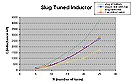
The diagram at the right shows the inductance relative to number of turns. There is 4 curves:
- 1. The slug is at the bottom of the can.
- 2. The top of the slug is in line with the top of the can.
- 3. The slug is totally removed.
- 4. A theoretically calculated curve.
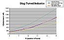
The diagram at the right is the same diagram as above but has different scale for the lower inductance. Conclution: As you can see from the diagram the theoretical value match the blue curve very well. The area between the Green and the Yellow curve is the span in wich you can adjust you inductance value.
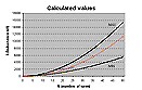
The diagram at the right shows the calculated values from MIN, MAX inductance. This page investigates some inductor I have got. As always one can never find andy info about the coils and there is no manufacture label either so I have to investigate more. All contribution to this page are most welcome I have made 4 coils with different number of turns. I made 6, 8, 12, ans 28 turns. There is a formula for coils I will use and I have the been using a LCR meter to measure the inductance of the 4 coils. The values are plotted in excel to form a curve and from the curve I can calculate the AL value. Formula : L (nH) = AL*n2 Where: L = inductance in nanohenrys AL = inductance factor n = number of turns This first diagram show the inductance with the screw-slug removed.
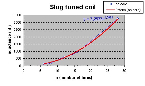 The red curve is made by excel and is a trendline. The inductance vary from 150nH to 3263nH.
The formula of the trendline is 3.2833 x 2.0681
If you compare this formula to he first one you can see the similarity.
The exponent is very close to 2 and the AL value will therefore be 3.28
The red curve is made by excel and is a trendline. The inductance vary from 150nH to 3263nH.
The formula of the trendline is 3.2833 x 2.0681
If you compare this formula to he first one you can see the similarity.
The exponent is very close to 2 and the AL value will therefore be 3.28The next diagram show the inductance with the screw-slug screwed to the bottom position.
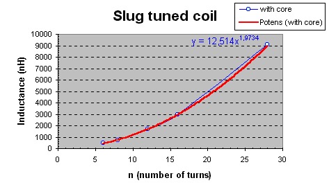 The red curve is made by excel and is a trendline.
The inductance vary from 457nH to 9113nH.
The formula of the trendline is 12.514 x 1.9734
The exponent is still very close to 2 and the AL value will therefore be 12.51
Conclusion: The ferrite slug core raise the AL from 3.3 to 12.5, depending on how deep it is screwed into the coil.
The tables below show the complete data. The position of the slug-core is in percent of the total lengt of the core. If there is no core the value is 0% and if the complete core is screwed into the coil the value is 100%
The red curve is made by excel and is a trendline.
The inductance vary from 457nH to 9113nH.
The formula of the trendline is 12.514 x 1.9734
The exponent is still very close to 2 and the AL value will therefore be 12.51
Conclusion: The ferrite slug core raise the AL from 3.3 to 12.5, depending on how deep it is screwed into the coil.
The tables below show the complete data. The position of the slug-core is in percent of the total lengt of the core. If there is no core the value is 0% and if the complete core is screwed into the coil the value is 100%
n = 6 | n = 8 |
| n = 12 | n = 16 |
| n = 28 |
